UNDERFLOOR HEATING INSTALLATION GUIDE
![]()
IMPORTANT POINTS TO REMEMBER
It is advisable when planning the layout of your new underfloor heating installation that you use 200mm spacings between the pipe centres, When you alter this measurement it affects the heat output in that area as closer spacings between pipe centres will increase the heat, whilst increasing the distance between the pipe centres will decrease the heat accordingly The recommended distance between pipe and wall is 100mm. To hold the pipe in place, we supply three options; firstly, the standard underfloor heating pipe clips on surfaces such as Kingspan.
These are designed to secure the pipe in place on a surface such as Kingspan foil backed insulation boards. Secondly, we supply grip rails(1 mtr) which provide pre-set spacings and can be placed using the self-adhesive strips along the undersid. Lastly, we stock aluminium spreader plates. These are used in suspended timber floors and provide pre-spaced grooves that run through the plates. When using a screed base, it is recommended that a 65mm sand and cement mix be spread over the pipes.
FUNCTION
The temperature control unit is the central component in monitoring and adjusting the water temperature supplied to the underfloor heating system.
The thermostatic mixing head controls the set flow temperature. Water temperature flowing into the system is monitored by the thermostatic mixing
head which will open/close as required. The thermostatic mixing head blends part of the cooler water returning from the underfloor heating circuit,
with the hot water flowing into the system directly from the boiler, thus ensuring a constant and ideal underfloor heating temperature.The required
water temperature can be adjusted to preference on the thermostatic mixing head. The thermostatic mixing head will open/close to blend water
directly back into the circuit and return some to the boiler for re-heating as required.
LAYING THE PIPE
 Starting at the manifold, lay the pipe out to the desired start location. Draw a line on the floor 100mm from the wall you wish to start from. Start at the mark on the floor and roll out the coil of pipe parallel with the wall, keeping the 100mm spacing from the wall. Clip the pipe down as you go at maximum spacings of 1m. To make a turn and run back parallel with the pipe just laid, form a bend in the pipe, clip down and begin rolling back whilst maintaining the required spacing between pipes (normally 200mm). If you are spacing closer than 200mm shallow out the bend to form a ‘C’ shape (light bulb shape), This should ensure the bend radius is no tighter than that achieved with a 200mm spacing.. Make sure to leave enough pipe on the roll to return back to the manifold.
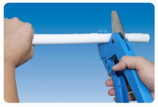
PREPARING THE PIPE
Use the recommended pipe cutter supplied to trim the pipe and use the reamer to clean the inside.
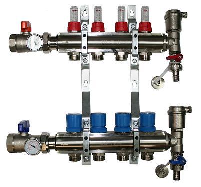
FILLING THE SYSTEM
Before you lay the screed fill the pipes with water and leave it under pressure.
You can connect to the manifold and check too. Check for any leaks and drop in pressure. The manifold with the flow gauges (the little clear plastic vials) is the flow manifold, the other manifold is the return manifold. Make sure to get all the air out of the system, it can take a bit of time to make sure it’s all out.
The manifold connects to the boiler like a radiator does. If your boiler is a high temperature output like a gas or oil boiler make sure to use some form of thermostatic control to reduce the temperature of the water. Use either a thermostatic blender valve, or if you need a pump too you can make this easier still with a thermostatic and pump blender kit.
CONTROL
For systems up to 15.00mtr2, connected to a radiator system, the use your existing controls is possible. This means the heating would come on and off with the radiators. If preferred you can use a thermostat and a motorised valve.
If you require more control over each zone or pipe run actuators can be used on the manifold. These can be controlled by a thermostat. You can have a separate thermostat for each port/zone if you require total control.
You will need to connect the actuators (at the manifold) to the thermostats (in the rooms) using either a wired or a wireless control. Wired systems tend to be more robust and economical. You need cables e.g. 1.5m 3 core flex) running from the manifolds to the thermostats, usually both are wired to a Wiring Centre Controller which can be put wherever it’s convenient (usually near to the manifold).
The flow through each port can be adjusted at the manifold to balance the system. The flow gauges indicate the rate of flow through each port. To alter these up and down pull up the lock ring (red) and turn the flow meter clockwise (reduce flow) or anti-clockwise (increase flow). Work on 1 zone at a time to keep the process a little simpler. Close all the ports by leaving the actuators off the manifold and then connect one at a time. Leave the pump running by wiring it up to the mains and energise each actuator. Make sure hot water is coming through, Alter the flow adjuster to see the effect and do the same with the thermostatic valve if you have one. Finally, balance not just the zone itself but the zones against each other.
If you have a zone with no flow, make sure there is no air block or any obstruction in the manifold. When everything is attached including the thermostats and the actuators check the operation of each room by altering the room stat to ensure each actuator is working correctly. Ensure you give them time to perform their duties.
Try not to mess around with the thermostat all the time. Force too much heat into the floor, you will be getting up to turn the stat down. Similarly, if you push too little then the room will never be warm. It is difficult to get a good setup in the summerheat. Preferrably, wait until it gets cooler to get it right. With underfloor heating, patience can ensure the perfect balance.